| Bill of Materials (per goal) |
| (1) Crossbar |
(6) 1/2" x 1" Hex Bolt |
| (2) Upright Weldment Note: There is (1) left and (1) right Upright |
(2) 1/2" x 6 1/2" Hex Bolt |
| (2) Corner Splice |
(6) 1/2" Lockwasher |
| (2) Backstay #1 (portable only) |
(2) 1/2" Centerlock Nut |
| (2) Backstay #2 (portable only) |
(4) 3/8" x 1 1/4" Hex Bolt |
| (2) Back Bar (portable only) |
(8) 3/8" x 1 1/4" Carriage Bolt |
| (1) Ground Bar (portable only) |
(6) 3/8" x 2 1/2" Hex Bolt |
| (2) Wheel Assembly (portable only) |
(6) 3/8" x 3" Hex Bolt |
| (2) Backstay Splice (portable only) |
(24) 3/8" Flatwasher |
| (4) Corkscrew Ground Stakes (portable only) |
(22) 3/8" Lockwasher |
| (2) European Backstay (semi / permanent only) |
(18) 3/8" Hex Nut |
| (2) Ground Stem (semi / permanent only) |
(2) Optional Padding Spacer |
| (4) Net Stakes (semi / permanent only) |
|
| 1. |
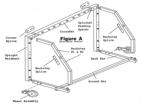
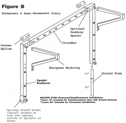
Unpack all components. Identify each piece based on either Figure A (portable goal) or Figure B (permanent/semi-permanent goal). |
| 2. |
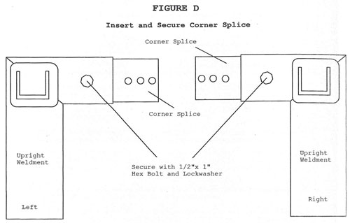
First, using (2) ½”x 1” hex bolts and (2) ½” lockwashers, secure (1) Corner Splice into each Upright as shown in Figure D. (Use 1 hex bolt and lockwasher on each Corner Splice) Note: The Corner Splice is a tight fit, some paint may scrape off when inserting Corner Splice into Upright. |
| 3. |
Then, using (4) ½”x 1” hex bolts and (4) ½” lockwashers provided, attach the UPRIGHT WELDMENTS to the CROSSBAR as shown in Figures A & B. |
| |
ATTENTION: There is a LEFT UPRIGHT WELDMENT and a RIGHT UPRIGHT WELDMENT. The welded attachment channel used to attach backstay to Upright should face up toward sky (see figures A & B) Additionally, if you purchased upright padding with your soccer goal(s) be sure to include the padding spacer as shown in the diagram. NOTE: IF YOU DO NOT PLAN TO PAD SOCCER UPRIGHTS, DO NOT USE PADDING SPACERS!
STOP! If you are performing a PERMANENT OR SEMI-PERMANENT soccer installation, skip down to step number 13. PORTABLE (roll-around) installations proceed with step 4 below. |
| 4. |
Use (1) BACKSTAY SPLICE to assemble BACKSTAY #1 to BACKSTAY #2. Do this by inserting BACKSTAY SPLICE equally into #1 & #2 then secure using (2) 3/8”x 2 ½” hex bolts, (4) 3/8” flatwashers, (2) 3/8” lockwashers and (2) 3/8” hex nuts. REPEAT step to build second backstay assembly.
TIP: BACKSTAY #1 is the piece that has a 49” leg. The 49” side is the TOP of the backstay. If you purchased a MINI model, your BACKSTAY #1 & #2 are interchangeable. |
| 5. |
With your CROSSBAR/UPRIGHT assembly lying face down on the ground attach (1) BACK BAR to bottom end of both UPRIGHTS using (1) 3/8” x 3” hex bolt, (2) 3/8” flatwashers, (1) lockwasher and (1) hex nut. |
| 6. |
Next, attach your BACKSTAY ASSEMBLY to the top corner of the UPRIGHT WELDMENT using (1) 3/8”x 3” hex nut, flatwashers, lockwasher and hex nut. Remember, the 49” (25” Mini) long end of the BACKSTAY is the end to attach to the UPRIGHT WELDMENT. Attach opposite end of BACKSTAY to BACK BAR using (1) 3/8” x 2 ½” hex bolt, flatwashers, lockwasher and hex nut. |
| 7. |
Slide GROUND BAR into position and attach as far back (toward back of soccer goal) as possible. Use (1) 3/8” x 3” hex bolt, flatwashers, lockwasher and hex nut at each end of GROUND BAR to secure in place.
NOTE: GROUND BAR is adjustable forward and back along BACK BAR to allow for clearance of football goalposts or any other obstruction that may impede proper placement of soccer goal. |
| 8. |
CAREFULLY using at least two people, stand goal to its upright, playing position. |
| 9. |
Using (1) ½” x 6 ½” hex bolt and (1) ½” centerlock nut, secure each WHEEL ASSEMBLY to the left and right sides of unit as shown in FIGURE A. TO TRANSPORT: Flip both wheels forward and secure in place using cotterless pin. Lift GROUND BAR from backside of unit to roll. Flip both wheels back for play. Store pin in the welded storage tube located on WHEEL ASSEMBLY. |
| 10. |
Check to make sure all hardware has been adequately tightened. |
11.
|
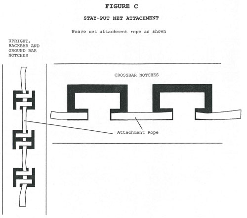
Drape net over unit and secure using First Team’s exclusive “STAY-PUT” net attachment slots as shown in FIGURE C. |
| 12. |
Position unit and secure to ground at four points along the GROUND BAR using the (4) CORKSCREW GROUND STAKES provided.
YOUR GOLDEN GOAL PORTABLE SOCCER GOAL IS COMPLETE! ALWAYS OBSERVE AND OBEY ALL RECOMMENDATIONS AND WARNINGS!!!
SEMI-PERMANENT & PERMANENT INSTALLATIONS PROCEED FROM THIS POINT: |
| 13. |
Determine if you are performing a PERMANENT or SEMI-PERMANENT soccer goal installation. If this is a SEMI-PERMANENT you should have received some small boxes labeled “Ground Sockets” (2) per soccer goal. These “GROUND SOCKETS” allow you to remove the soccer goal from the ground when not in use. Alternatively, a PERMANENT installation results in UPRIGHTS that are cemented permanently in place and cannot be removed. Once you are certain which installation you are performing, proceed with step number 13. |
| 14. |
Place (1) 3/8” lockwasher onto each of the (8) 3/8” x 1 ¼” carriage bolts. Next thread a 3/8” hex nut onto each carriage bolt to within ½” of the head of the carriage bolt. |
| 15. |
At the bottom, open end of each upright you will find a “star” shaped cutout welded inside the 4”x4” aluminum UPRIGHT. Insert the head of one carriage bolt into the center of the “star” cutout and slide the bolt outward to the extreme end of one of the four points of the “star.” Tighten nut. Repeat until one bolt is in place at all four “points’ of the star on each UPRIGHT.
NOTE: When properly assembled, the 3/8” lockwasher & 3/8” nut should be visible from the bottom (open) end of the UPRIGHT. If you have questions call First Team toll-free 1-888-884-6677. |
| 16. |
If you are performing a PERMANENT installation, insert the GROUND STEM into the UPRIGHT so the 36” long portion is extended out the bottom of the UPRIGHT. Insert the GROUND STEM careful to line up the holes in the GROUND STEM mounting plate with the 3/8” carriage bolts protruding from the bottom of the UPRIGHT. Secure (1) GROUND STEM to each UPRIGHT using (4) 3/8” lockwashers and (4) 3/8” hex nuts. |
| 17. |
If you are perfoming a SEMI-PERMANENT installation, follow the step discussed in STEP 16. However, insert GROUND STEM into UPRIGHT so 10” long portion is extended out the bottom of the UPRIGHT.
ATTENTION!!!! ATTENTION!!! ATTENTION!!!
VERY IMPORTANT!!! READ CAREFULLY BEFORE PROCEEDING!!! |
| 18. |
If you are performing a SEMI-PERMANENT installation, REMOVE AND INSTALL GROUND SOCKETS NOW! Installation instructions for GROUND SOCKETS are provided with the sockets. Remove and install the sockets per the installation instructions. Be sure to measure the “CENTER-TO-CENTER distance of your UPRIGHTS. This will be the distance to use when determining how far apart to cement your GROUND SOCKETS. Installations using GROUND SOCKETS should wait for 7 days to allow cement to cure before completing installation. After 7 days, you may proceed with installation starting with Step 21.
PERMANENT installations may proceed immediately with step 18. |
| 19. |
Measure the “CENTER-TO-CENTER” distance from UPRIGHT TO UPRIGHT. Locate and dig (2) 12”x 36” deep holes where you want soccer goal to be permanently installed. The CENTER-TO-CENTER distance from hole to hole should match the CENTER-TO-CENTER distance of your soccer goal UPRIGHTS. |
| 20. |
Place CROSSBAR/UPRIGHT assembly into holes making certain you have the GOALFACE toward the playing field! Also, make certain the bottom of each UPRIGHT is flush with playing surface. 4”x4” square portion of UPRIGHT should not extend below playing surface. |
| 21. |
Brace unit and fill both holes with concrete. Secure unit making sure UPRIGHTS are straight and plumb and the overall unit is square to the playing field. WAIT!!! WAIT!!! WAIT!!! Allow concrete to cure for 7 days before proceeding. |
| 22. |
(Semi-Permanent Installers may now open GROUND SOCKETS and insert GROUND STEM/UPRIGHT assembly into SOCKETS) Place EUROPEAN BACKSTAY into mounting channel on UPRIGHT WELDMENT as shown in Figure B and secure each side using (1) 3/8” x 3” hex bolt, (2) 3/8” flatwashers, (1) 3/8” lockwasher and (1) 3/8” hex nut. |
| 23. |
Secure the bottom side of each EUROPEAN BACKSTAY into the 3/8” threaded holes provided in each UPRIGHT using (2) 3/8” x 1 ¼” Hex Bolt, (2) 3/8” flatwashers and (2) 3/8” lockwashers. |
| 24. |
Check all hardware to insure it has been adequately tightened. |
| 25. |
Drape net over unit and secure using First Team’s exclusive “STAY-PUT” net attachment slots as shown in FIGURE C. |
| 26. |
Secure Net to ground using the (8) NET STAKES provided with your unit. First Team recommends staking the net twice on each side and four times along the backside. |
| 27. |
YOUR GOLDEN GOAL PERMANENT OR SEMI-PERMANENT SOCCER GOAL IS COMPLETE!
ALWAYS OBSERVE AND OBEY ALL RECOMMENDATIONS AND WARNINGS!!!
|